DC Motors Formulas and Back EMF Equation
EMF Equation of a DC Motor
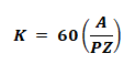
The basic DC motor’s E.M.F equation is given below.
Eb = PΦNZ / 60A
Where;
- P is the number of poles
- Ф is the Flux per pole
- N is the Speed of motor in (RPM)
- Z is the Number of conductors
- A is the Number of parallel paths
In a final designed motor, the number of poles “P”, conductors “Z” and parallel paths “A” are fixed, therefore, the following quantities and parameters remains constant.
Eb ∝ ΦN
Eb = kΦN ….. (1)
Where k is the Proportionality constant
The back EMF of DC motor equation can also be defined as
Eb = V – IaRa ….. (2)
Where;
- V is the supply voltage
- Ia is the Armature current
- Ra is the Armature resistance
Now compare both equations of (1) and (2);
kΦN = V – IaRa
k = N = V – IaRa / kΦ
The above relation shows that the speed of a DC motor can be controlled through change in voltage, flux and armature resistance.
Related Posts:

Voltage Equation of a DC Motor
Input Voltage provided to the motor armature performs the following two tasks:
- Controls the induced Back E.M.F “Eb” of the Motor.
- Provides supply to the Ohmic IaRa drop.
i.e.
V = Eb + IaRa ….. (1)
Where
- Eb = Back E.M.F
- IaRa = Armature Current X Armature Resistance
The above relation is known as “Voltage Equation of the DC Motor”.
Power Equation of a DC Motor
Multiplying both sides of Voltage Equation (1) by Ia , we get the power equation of a DC motor as follow.
VIa= EbIa + Ia2 Ra ….. (2)
Where,
- VIa = Input Power supply (Armature Input)
- EbIa = Mechanical Power developed in Armature (Armature Output)
- Ia2 Ra = Power loss in armature (Armature Copper (Cu) Loss)
Related Posts:
- Motor Starter – Types of Motor Starters and Motor Starting Methods
- Direct Online Starter – DOL Starter Wiring Diagram for Motors
- Cable Size Calculation for LT & HT Motors
Shunt Motor:
Voltage Equation of Shunt Motor:
V = Eb + Ia x Ra
Where
- V is the terminal voltage
- Eb is the induced back e.m.f
- Ia is the armature current
- Ra is the armature resistance
The Shunt Field Current:
Ish = V / Rsh
Where
- Ish is the shunt field current
- Rsh is the shunt field resistance
Induced Back EMF:
The armature induced voltage Eb is proportional to the speed & it is given by:
Eb = kfΦω
Where
- Kf is a constant based on machine construction
- Φ is the magnetic flux
- ω is the angular speed
Maximum Power Condition:
The output mechanical power is of shunt dc motor is maximum when the back e.m.f. produced is equal to the half of its terminal voltage i.e.
Eb = V/2
Torque & Speed:

And
Where
- N = speed of the motor in RPM
- P = No of poles
- Z = number of armature conductors
- A = number of armature parallel path
Related Posts:
Speed Regulation:
It is a term expressed in percentage that shows the change of motor speed when the load is changed.
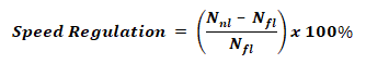
Where
- Nnl = No load speed of the motor
- Nfl = Full load speed of the motor
Input & Output Power:
Pin = VIa
Pout = T ω
Where
- V = terminal voltage
- Ia = armature current
- T = torque of the motor
- ω = speed of the motor
Related Posts:
- Servo Motor – Types, Construction, Working, Controlling & Applications
- Brushless DC Motor (BLDC) – Construction, Working Principle & Applications
- Stepper Motor – Types, Construction, Operation & Applications
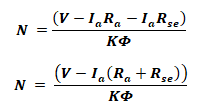
Series Motor:
Voltage Equation Of Series Motor:
V = Ea + Ia Ra + IaRse
V = Ea + Ia(Ra+Rse)
Where
- Ea is the armature induced voltage
- Ia is the armature current
- Ra is the armature resistance
- Rse is the series field resistance
Armature Induced Voltage & Torque:
The armature induced voltage Ea is proportional to the speed and armature current whereas the torque Ta of series motor is directly proportional to the square of armature current & it is given by:
Ea = kfΦωIa
Ta = kf Φ Ia2
Where
- Kf is a constant based on machine construction
- Φ is the magnetic flux
- ω is the angular speed
Speed of Series Motor:
Input & Output Power
The input power of a series motor is given by:
Pin = VIa
The output power is given by
Pout = ωT
Related Posts:
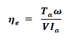
Efficiency Of DC Motor:
The different motor efficiencies can be found by the following formulas and equations
Electrical Efficiency:
ηe = Converted power in armature / Input electrical Power
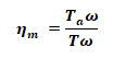
Mechanical Efficiency:
ηm = Converted power in armature / output mechanical power
Overall Efficiency:
η = Output mechanical Power / Input electrical Power
η = (Input Power – Total losses) / Input Power
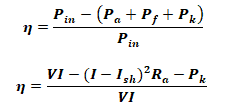
Where
- Pout is the useful output power
- Pa is the armature copper loss
- Pf is the field copper loss
- Pk is the constant losses that contains core losses & mechanical losses
Related Formulas and Equations Posts:
- Types of Electric Motors – Classification of AC, DC & Special Motors
- Applications of Electric Motors
- DC Machine – Construction, Working, Types and Applications
- Single-Phase Induction Motor – Construction, Working, Types & Applications
- Three-Phase Induction Motor – Construction, Working, Types & Applications
- Induction Motor & Linear Induction Motors Formulas & Equations
- Transformer Formulas and Equations
- Basic Electrical Engineering Formulas and Equations
- Basic Electrical Quantities Formulas
- Power Formulas in DC and AC Single-Phase & Three-Phase Circuits
- Electrical & Electronics Engineering Formulas & Equations
- Electric Motors Symbols
-
 What is Sag in Overhead Power Transmission Lines?
-
 Why is the Ground Wire Always Positioned Above the Overhead Power Lines?
-
 How Many Poles and Towers are Situated Within a 1-km Span?
-
 Why are Overhead Power Transmission Lines Not Insulated?
-
 How to Wire Twin Timer for Repeated ON-Delay in Cycle Mode?
-
 Wire Twin Timer in Repeat Cycle & One-Shot Mode for 120V/240V Motors?